If you’re looking to Sell Fluke 40 HandHeld Power Harmonics Analyzer
Worldwide there is an increasing concern about the effects of power harmonics on electrical systems.Using their knowledge of hand held test equipmentand digital signal processing techniques Flukedeveloped these affordable, practical tools todiagnose power harmonics problems.
What are power harmonics?
Power harmonics are caused by non-linear loads suchas inverters (drives) and switch mode power supplies,even electronic ballasts for fluorescent lighting.Linear loads draw current in sine-waves at the supplyfrequency, non-linear loads do not, theseelectronically controlled loads tend to draw current inshort pulses causing a distorted current waveform tobe drawn from the supply.
AC theory demonstrates that non-linear currentconsumption actually consists of a sum of current at thesupply frequency and at multiples of the supplyfrequency. These multiples are the harmonics. Forexample if the supply frequency is 50Hz then thesecond harmonic is 100Hz and the third harmonic is150Hz, and so on. Because the electrical distributionsystem has a source impedance greater than 0W, largeharmonic currents will cause harmonics to appear onthe supply voltage. When this rises to significant levelsit may cause additional problems.
Why are power harmonics a problem?
Symptoms of harmonics usually show up in the powerdistribution equipment that support the non-linearloads. There are two basic types of non-linear loads -single-phase and three-phase. Single-phase nonlinearloads are prevalent in offices, while three-phaseloads are widespread in industrial plants.
Each component of the power distribution systemmanifests the effects of harmonics a little differently.Yet all are subject to damage and inefficientperformance.
Neutral conductors
In a 3-phase, 4-wire system, neutral conductors can beseverely affected by non-linear loads connected tosingle-phase branch circuits. Under normal conditionsfor a balanced linear load, the fundamental 50Hzportion of the phase currents will cancel in the neutralconductor.
In a 4-wire system with single-phase non-linear loads,certain odd numbered harmonics called triplens (oddmultiples of the third harmonic: 3rd, 9th, 15th etc.) donot cancel, but rather add together in the neutralconductor. In systems with many single-phase nonlinearloads, the neutral current can actually exceedthe phase current. The danger here is excessiveoverheating because there is no circuit breaker in theneutral conductor to limit the current as there are in thephase conductors.
Excessive current in the neutral conductor can alsocause higher than normal voltage drops between theneutral conductor and ground at the 240V mainssockets.
Circuit breakers
Common thermal-magnetic circuit breakers use a bimetallictrip mechanism which responds to the heatingeffect of the circuit current. It is designed to respond tothe true rms value of the current waveform andtherefore will trip when it gets too hot. This type ofbreaker has a better chance of protecting againstharmonic current overloads.
A peak sensing electronic trip circuit breakerresponds to the peak of current waveform. As a resultit won’t always respond properly to harmoniccurrents. Since the peak of the harmonic current isusually higher than normal, this type of circuit breakermay trip prematurely at a low current. If the peak islower than normal the breaker may fail to trip when itshould.
Bus bars and connecting lugs
Neutral bus bars and connecting lugs are sized tocarry the full value of the rated phase current. Theycan become overloaded when the neutral conductorsare overloaded with the additional sum of the triplenharmonics.
Electrical panels
Harmonics can occasionally effect electrical panels.Panels that are designed for use with 50Hz currentmay become resonant to the magnetic field generatedby higher frequency harmonic currents. If thishappens a panel can vibrate and emit a buzzing soundat the harmonic frequency.
Transformers
Where a substation has a delta-why transformer, thereare two potential problems caused by harmonics.Firstly, single phase non-linear loads produce triplenharmonics which algebraically add up in the neutral.When this neutral current reaches the transformer it isreflected into the delta primary winding where itcirculates and causes overheating which may lead totransformer failures.
Secondly, since transformers are rated for 50Hz useharmonic currents can cause core losses and copperlosses. Higher frequency harmonics cause increasedcore loss due to eddy currents and hysteresis,resulting in more heating than would occur at the same50Hz current. These heating effects mean thattransformers need to be derated for harmonic loads orreplaced with specially designed transformers.
Generators
Standby generators are subject to the same kind ofoverheating problems as transformers. Because theyprovide emergency back-up for harmonic producingloads such as data processing equipment they areoften even more vulnerable. In addition tooverheating, certain types of harmonics producedistortion at the zero crossing of the current waveformwhich causes interference and instability for thegenerators control circuits.
Motors
Where there is a significant harmonic voltage presenton the supply to a motor, certain harmonics can causea rotating field that opposes the rotation of the motor.Although this may have little apparent effect on therotation of the motor, it can cause overheating andsubsequent damage to the motor.
Buying, Selling, Trading Fluke 40
Power factor
Harmonics is not only a major contributor to adversepower factor, but can also cause overheating of powerfactor correction capacitors.
Classification of harmonics
Each harmonic has a name, frequency and sequence.The sequence refers to phasor rotation with respect tothe fundamental (F), i.e. in an induction motor, apositive sequence harmonic would generate amagnetic field that rotated in the same direction as thefundamental. A negative sequence harmonic wouldrotate in the reverse direction. The first nine harmonicsalong with their effects are listed below.
When selected a “Record function stores Max, Min,and Average readings that can be easily accessedwith the cursor keys when on a text screen.** Zero sequence harmonics (odd multiples of the 3rd) are called “Triplens” (3rd, 9th, 15th, 21st, etc.)
Fluke 40 and 41 power harmonic meters
The Fluke 40 and 41 measure the voltage and current (via the 500A current transformer supplied) of thecircuit under test. It can then display the voltage,current or power as a waveform, a bargraph of theharmonics or as a digital display.
Fluke have designed these harmonics analysers to besimple to use, all functions and displays are easilyaccessed via the fewest possible key presses, so thereare no menus to work through.
The tester uses a set of nine multi-purpose screens topresent each type of measurement (Volts, Amps orWatts) as a waveform, a relational bar chart ofharmonics, or a series of digital (text) readouts. Onekey selects between Volts, Amps and Watts, whilstanother selects the display type. With multiple valuesand computations on each screen it becomes simple toaccess all the information about the power, voltage orcurrent at the test point.
Specifications
Minimum input levels ______5V rms (using VØ reference)
or 1A rms (using AØ reference)
Voltage (true rms)
Input range__________________ 0.0 to 600.0V rms (ac + dc)
0.0V to ±933 peak
Basic accuracy (fundamental, 5-65Hz):
rms_____________________________ ±(0.3% + 2 digits)
peak, dc___________________________ ±(2% + 3 digits)
Input impedance _______________________ 1MW, balanced
Crest factor _______________>3.0 below 300V, 1.56 at 600V
Current with mV/A input (true rms)
Input range _________________ 1.00 to 1000A rms (ac + dc)
1.0 to ±2000A peak
Basic accuracy (fundamental, 5-65Hz):
rms ________________ ±(0.3% + 3 digits) + probe specs
Crest factor_______________ >3.0 below 600A, 2.0 @ 1000A
80i-500s current probe (supplied)
1 to 20A ac ___________________________ ±(5% + 0.3A)
20 to 100A ac ________________________________ ±5%
100 to 500A ac _______________________________ ±2%
Power (watts and volt-amps) with 1mV/A input
Range_______________________ 0 to 600kW (kVA) average
0 to 2000 kW (kVA) peak
Basic accuracy (fundamental, 5Hz-65Hz):
Active power__________±(1% + 4 digits) + probe specs
Harmonics accuracy (cursor data)
Volts:
Fundamental to 15th harmonic:
Volts _____________________________ ± (1% + 2 digits)
Phase _______________________________________ ± 2°
16th to 31st harmonic:
Volts ______________________________±(2% + 3 digits)
Phase _______________________________________±10°
Amps and Watts:
Fundamental to 15th harmonic:
Amps or Watts _______ ± (2% + 3 digits) + probe specs
16th to 31st harmonic:
Amps or Watts _______ ± (3% + 4 digits) + probe specs
Other measurement specifications
Frequency _____________________ 5.00Hz-99.9Hz ±0.3Hz
Input bandwidth (-0.5dB) _____________ dc 5Hz to 2.1 KHz
Crest factor (CF range) _____________________ 1.00 to 5.00
Power factor (PF) __________________________ 0.00 to 1.00
Displacement power factor _________________ 0.00 to 1.00
Phase measurement range _________________ -179 to 180°
K-factor (KF) range (Model 41) _____________ 1.00 to 30.00
General specifications
Size _________ 9.2 3 3.9 3 2.5 inches (234 3 100 3 64mm)
Weight ____________________________________2.0 lb(1kg)
Battery:
Type ____________ 4 alkaline “C” cells ANSI/NEDA-14A
IEC-LR14 (supplied)
Life __________________24 hours minimum (continuous)
Temperature:
Operating ___________________ 32° to 122°F (0 to 50°C)
Storage ____________________ -4° to 140°F (20 to 60°C)
Temperature coefficient ___0.1 3 specified accuracy per °C
(0 to 18°C, 28 to 50°C)
Humidity:
Operating _____________32 to 86°F (0 to 30°C) 90%
86 to 104°F (30 to 40°C) 75%
104 to 122°F (40 to 50°C)45%
Storage _____________________________________ 90%
Altitude:
Operating _______________________15,000 feet (4.6km)
Storage _________________________ 40,000 feet (12km)
Shock and vibration ____________ Per MIL-T-28800, class 3
Electromagnetic compatibility
RF emissions ______________ EN 50081-1 commercial limits
FCC Part 15 Class B
VFG 243-1991
RF susceptibility _____________ EN 50082-2 Industrial limits
Case ________________________ Drip-proof and dust-proof
Display
Type _______________________ Super twisted liquid crystal
Contrast ______________________________ User-adjustable
Backlight ________________________________________ Yes
Safety
Designed for 600V measurements on industrial power
distribution circuits
Overload protection:
Voltage or current probe input ________ 600V maximum
Surge protection ________________ 6kV per IEC 1010-1
Max. voltage isolation to earth __ 600V from any terminal
Protection levels __________ IEC 1010-1, Pollution Degree 2
Installation Category III,
Material Group II, 600V
Protection class ___________________ Protection Class II as
described in IEC 1010-1, Annex H
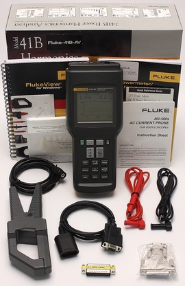
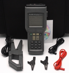
Includes:
- Fluke 40 HandHeld Power Harmonics Analyzer
- Fluke TL-24 Test Leads (1 Red – 1 Black)
- Fluke 80i-500s AC Current Clamp
- Fluke TP-20 Test Probes (1 Red – 1 Black)
- Fluke AC20 Test Clips (1 Red – 1 Black)
- Hard Copy User Manual
- Carrying Case
If you’re selling your Fluke 40 please fill out form on the right hand side of page.